
Updated 03/07/2019
Please join with us as we learn about electronics and the Arduino! Together through this series of tutorials we would like to share with you a journey of learning, exploration and fun with the Arduino system, and make some enjoyable, useful, interesting, useless and practical things.
So let’s get started…
During the first few posts, we will refer to the book:
- Getting Started with Arduino (Massimo Banzi)
and also assume a basic knowledge of electronics.
If you would prefer an off-line method of learning, or would like a great book on the topic – consider the book “Arduino Workshop” – it’s the best book on the market for a complete beginner to learn about Arduino.
First of all, let’s breakdown the whole system into the basic parts. From there we can build an understanding of what Arduino is all about.
Arduino is an open source physical computing platform based on a simple input/output board and a development environment that implements the Processing language (www.processing.org). Arduino can be used to develop standalone interactive objects, or be connected to software on your computer. [1]
So, we have hardware and software. Our hardware will be a personal computer that can run the Arduino IDE (integrated development environment) software; and the Arduino itself and the electronics to go with it.
Our software is the IDE – software very similar to a word-processor, but can send the Arduino program (or “sketch”) to the micro controller. These sketches are programs that are written in the processing language – which is similar to C. These are interpreted by a boot loader – software in the chip that allows it to understand your sketch. As the Arduino system is open source, anyone can purchase a blank micro controller and put the boot loader on it, or even write their own boot loader or modify the original one.
Now for the Arduino itself. But what do we mean by that? Let’s have a look…
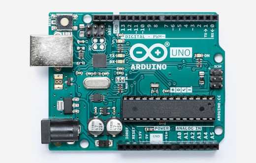
What we have is a microcontroller installed into a circuit board with a USB interface, a DC power socket, and many input and output lines (more about them later). Plus some LEDs for status reports, and other miscellaneous components. This board is the Uno, and uses the ATMega328 micro controller.
To summarise at this point – with an Arduino you can connect various forms of input and output, and create a program to process and respond to the inputs and outputs. For example, you could create a temperature alarm – when your room temperature rises above a set amount, the Arduino could sound an alarm.
Forms of input can include: buttons, switches, movement sensors, temperature sensors, light sensors, gas sensors (!), dials that you can turn (e.g. like a volume knob), wireless data receivers, etc. Forms of output can include: lights, noise-makers, motors, pumps, other circuits, liquid-crystal displays, etc. Basically anything that can be switched on or off, or controlled by electricity, can be controlled by an Arduino.
To make things easier, you can buy or make what is called a shield. This is an interface board that sits on top of your Arduino, and has various types of circuitry you can interface with. For example, an Ethernet network connection, a joystick for games or controlling a robot, or an LCD.
So that means with the right sketch, and the right hardware interface, and maybe a shield, you can do almost anything.
Great!
Thankfully that’s about all we need to learn at the moment. Now it is time to actually do something. You are going to need three things:
- A personal computer running Linux, MacOS or Windows with a USB port, with Internet access. Then again, if you’re reading this – you’re on the ‘net
- a USB cable that matches your board socket
- an Arduino or compatible board. Most boards should come with a USB cable, check before buying.
And now for the initial preparation – please install your Arduino IDE software using the instructions here.
How did you go? Did your LED blink? Were you mesmerised by it, staring blankly at all the blinky goodness? It’s ok, you can admit it – we all were the first time.
When working through this series of tutorials, some of the files you download will end with .pde or .ino. They’re both fine, the .pde extension was used for sketches written before Arduno IDE v1.0. You can load these and work with them as normal.
At this point I hope you realised that the Arduino can be powered by your computer’s USB port. However, if you want to use your programmed Arduino away from the computer, you will need a nice regulated plugpack or another source of power.
There is some really basic things to get started, however with respect to the Arduino creators, please refer to the book Getting Started with Arduino book until the end of page 38. You should be able to get that LED to blink on your own!
Exercise 0.1
Now let’s have some more blinky fun. Do you remember Knight Rider with David Hasselhoff? The ‘hoff drove a tricked-up Trans Am with some cool lights in the bonnet, a horizontal row with each light blinking in sequence from left to right to left…
Your mission, is to simply recreate this with your Arduino, using not one but eight LEDs. Blink them in an endless loop in the sequence 1-2-3-4-5-6-7-8-7-6-5-4-3-2-1-2-3-… with a delay of one second.
You will need:
- Your standard Arduino setup (computer, cable, Uno or compatible)
- 8 light emitting diodes (LEDs). Anything as long as they draw less than 40mA.
- 8 560 ohm 0.25 W resistors. They are to reduce the current to protect the LEDs
- a breadboard and some connecting wire
- a camera (optional) – to document your success!
Hint – make the delay a variable so you can alter it easily.
From your original flashing LED project in the book, the digital pin 13 was used. This time, you can use digital pins 2 to 9. The hardware side is easy – run a wire from each digital output pin to the anode of an LED, then put a 560 ohm resistor from the cathode back to ground.

Finally, here it is in action:
Now it is your turn to do something – write the code! But before you do that, plan what you want to do first (some old-schoolers would call the plan an algorithm). For example, for this exercise you might write something like…
- set all the pins I want to use as outputs
- create a variable to store the delay duration in milliseconds
- start an infinite loop
- turn on pin 2, wait for delay duration, turn it off
- turn on pin 3, wait for delay duration, turn it off
- repeat for pins 4 to 9
- then do the same thing but backwards down to pin 3
- end of infinite loop
So how did you go? Did it work first time? It’s ok if it didn’t, as you learn by doing and fixing your mistakes. Remember – if you have any questions, leave a comment at the bottom of this post and I will get back to you. But to save you time, here is the sketch:
/*
exercise 0.1 - KITT emulator!
 Created 03/07/2019
 http://tronixstuff.com...
 Blinks LEDs from output pin 2~9 in a forwards<>backward motion
 The circuit:
 an LED is connected to each output pin from 2 to 8, thence to a 560 ohm resistor, then to ground (pin 4 on the bottom left of the Arduino Duemilanove).
 based on an orginal by H. Barragan for the Wiring i/o board
 */
// The setup() method runs once, when the sketch starts
int del=100; // sets a default delay time, 100 milliseconds (one tenth of a second)
void setup()
{
  // initialize the digital pins as outputs:
  // later on there will be easier ways to do this
  pinMode(2, OUTPUT);
  pinMode(3, OUTPUT);
  pinMode(4, OUTPUT);
  pinMode(5, OUTPUT);
  pinMode(6, OUTPUT);
  pinMode(7, OUTPUT);
  pinMode(8, OUTPUT);
  pinMode(9, OUTPUT);
}
// the loop() method repeats indefinitely until you turn off the power
void loop()
{
  digitalWrite(2, HIGH);   // turn on LED on pin 2
  delay(del);              // wait (length determined by value of 'del')
  digitalWrite(2, LOW);    // turn it off
  digitalWrite(3, HIGH);   // turn on LED on pin 3
  delay(del);              // wait
  digitalWrite(3, LOW);    // turn it off
  digitalWrite(4, HIGH);   // turn on LED on pin 4
  delay(del);              // wait
  digitalWrite(4, LOW);    // turn it off
  digitalWrite(5, HIGH);   // turn on LED on pin 5
  delay(del);              // wait
  digitalWrite(5, LOW);    // turn it off
  digitalWrite(6, HIGH);   // turn on LED on pin 6
  delay(del);              // wait
  digitalWrite(6, LOW);    // turn it off
  digitalWrite(7, HIGH);   // turn on LED on pin 7
  delay(del);              // wait
  digitalWrite(7, LOW);    // turn it off
  digitalWrite(8, HIGH);   // turn on LED on pin 8
  delay(del);              // wait
  digitalWrite(8, LOW);    // turn it off
  digitalWrite(9, HIGH);   // turn on LED on pin 9
  delay(del);              // wait
  digitalWrite(9, LOW);    // turn it off
  digitalWrite(8, HIGH);   // turn on LED on pin 8
  delay(del);              // wait
  digitalWrite(8, LOW);    // turn it off
  digitalWrite(7, HIGH);   // turn on LED on pin 7
  delay(del);              // wait
  digitalWrite(7, LOW);    // turn it off
  digitalWrite(6, HIGH);   // turn on LED on pin 6
  delay(del);              // wait
  digitalWrite(6, LOW);    // turn it off
  digitalWrite(5, HIGH);   // turn on LED on pin 5
  delay(del);              // wait
  digitalWrite(5, LOW);    // turn it off
  digitalWrite(4, HIGH);   // turn on LED on pin 4
  delay(del);              // wait
  digitalWrite(4, LOW);    // turn it off
  digitalWrite(3, HIGH);   // turn on LED on pin 3
  delay(del);              // wait
  digitalWrite(3, LOW);    // turn it off
}
So there you have it. Today you have learned how to set up a computer to program your Arduino, and written some sketches to create outputs based on your design. Although it wasn’t that much, we have to start somewhere… but great things will follow. Like chapter one!
This website is brought to you by PMD Way – the online store for makers, with free delivery worldwide.
Notes:
[1] from “Getting Started with Arduino” by Massimo Banzi (O’Reilly).
